
The History of the M1 Garand —
The Early Designs and Initial Adoption
Early Designs
The Ordnance Department announced eight principal requirements for the next generation of semi-automatic weapons in 1921. This new design was to replace the M1903 Springfield bolt-action rifle, which had a limited rate of fire and heavy recoil. The M1903 had been in service since 1903, firing (after a redesign) the new Springfield .30-06 cartridge. The Ordnance Department required that any new design would have to:
- Weigh no more than nine pounds.
- Be well-balanced and adapted to shoulder firing.
- Have a magazine fed from clips or charges.
- Be simple, strong, compact, and easy to manufacture.
- Be entirely semi-automatic, firing one shot with each squeeze of the trigger.
- Use the .30 caliber service cartridge.
- Be designed so as to preclude the possibility of premature unlocking.
- Function properly without any need for special oil, grease, or other material applied to the cartridge.
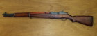
The History of the M1 Garand Rifle
The Early Designs and Initial Adoption
Springfield Armory and World War II Production
The most promising semi-automatic design was a gas-operated system. Some of the expanding gas driving the bullet down the barrel would be used to unlock and drive back the bolt, ejecting the spent case. A spring would then bring the bolt back forward, stripping a fresh round from the magazine and inserting it into the firing chamber.
Garand's eventual design included a small port near the muzzle allowing some gas to enter the front of a short cylinder below the barrel. That gas drove back a piston forming the far end of the operating rod. The operating rod is a long rod of complex shape stretching from near the muzzle back to the bolt behind the chamber. The motion of the operating rod twisted and pulled back the bolt, and then a spring largely contained within the operating rod returned both to their normal or "in battery" positions.
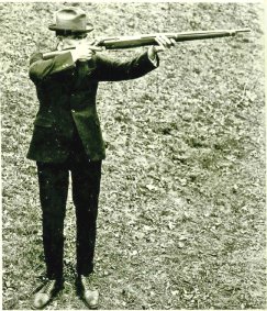
John Garand with his Model 1921 rifle design.
The magazine had to be fixed and non-protruding. It was believed that a detachable magazine would be easily lost, and would degrade performance by increased clogging by dirt and debris. Also, a protruding magazine would complicate the existing manual-of-arms drills.
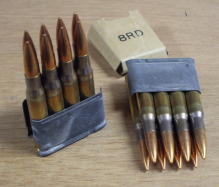
Garand designed an en-bloc clip, stamped from spring steel and tightly holding eight rounds. The cartridges and the clip itself were inserted into the magazine. The empty clip would be ejected along with the last case and the follower mechanism would lock the bolt open. Another clip would be inserted into the magazine, the bolt drawn back with the operating handle, and allowed to slam home while chambering the first round from the fresh clip.
This design met the Ordnance Department's requirements, but it added weight and complexity.
An empty clip ejected with a distinctive metallic "ping". There were reports in both World War II and the Korean War that enemy infantry would listen for that noise to alert them to an empty M1 rifle and the possibility of rushing the American position. In turn, there were stories of Americans throwing an empty clip while firing the first of eight rounds in a fresh clip — possibly luring the enemy out of cover to face a nearly full M1.
The U.S. Army's Aberdeen Proving Ground experimented with clips made of various materials, including plastic, to avoid the distinctive sound made by a spring steel clip. Nothing came of these experiments. Given the available plastic technology of the 1940s through the early 1950s, that was probably a good thing!
The specifications changed over the coming years. The Army introduced the .276 caliber cartridge for testing in 1923. It was thought that the smaller caliber and lighter cartridge would provide an advantage by allowing each man to carry more rounds. Garand was asked to develop a .276 caliber rifle design in 1927. But then Douglas MacArthur, Chief of Staff, decided in 1932 to abandon the .276 project and go back to .30 caliber, partly because of the large existing stocks of .30 M1 ball ammunition.
Further difficulties were caused by the makeup of the Ordnance Committee, as it was made up of representatives of the Army's main branches and each of them wanted the new rifle to be optimized for their branch — infantry, cavalry, and tank crews. From the production end, Garand was directed to use as many M1903 Springfield parts as possible.
Garand developed a number of designs, starting with his fully automatic Model 1919. The following designs were semiautomatic only, varying as to cycling operation (primer versus gas), bolt design (rotating versus pivoting and locking into place at the rear), caliber (.276 versus .30), magazine (20 to 30 round detachable, fixed 5-round magazine in the receiver, and clip fed), and other details. See the U.S. National Park Service's Springfield Armory National Historic Site for details of several of the designs.
Garand's designs did not represent any large jump in technology, they were based on what had come before and were consistently simple, stable, and reliable.
The primer-operated system is unfamiliar today. It was based on a cartridge in which the primer is free to move backwards several thousandths of an inch to operate a mechanism that unlocks the bolt and allows it to cycle. With a change to slower-burning powder, this was not a practical design. And, the standardized .30 caliber cartridge did not support a primer that was not crimped firmly in place.
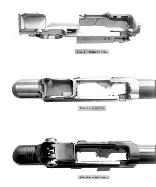
Top-bottom: The receivers of Garand's M1926, T1, and T1E1 designs.

Amazon 1934044253
Amazon 0889351104
The direct lineage of the design goes back to Garand's M1926, Garand's first gas-operated design, which became the T1. It was designed in 1926, but it was not built until 1930 because of the Ordnance Committee's 1927-1932 plan for the .276 caliber round.
The T1E1 was built in 1931. It was a single trial unit with a weak bolt that broke during testing.
The T1E2 was really a T1E1 with a redesigned bolt. This modification of Garand's 1926 design was accepted and designated as the US Semiautomatic Rifle, M1 on 3 August 1933.
Eighty M1 rifles were built for testing in 1934. These were called the "Model Shop" M1s. Construction started in April, and seventy-five were shipped out for testing in May. A number of problems were reported, requiring further slight modification to the design.
The modified M1 design was cleared for procurement on 7 November 1935, the design was standardized on 9 January 1936, and on 21 July 1937 the first production model (serial number 81, following the Model Shop units) finished the testing sequence of proof firing, function firing, and firing for accuracy.

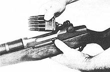
John Garand demonstrating his design's en-bloc clip loading.
Production was slow to start. There were no deliveries to the Army until September, 1937. Production then was ten rifles per day. By September 1939, when Germany had invaded Poland and started open military action in World War II, Springfield Armory's production was still only 100 units per day. By January 1941, a month after Japan's attack on Pearl Harbor and the U.S. entry into the war, it was six hundred per day. At its peak, Springfield Armory was producing four thousand rifles per day. The cost was $200 per rifle in the beginning, dropping to just $26 each by 1945.
There was another redesign in 1939. The original gas trap design was replaced with a simpler and more reliable gas port and cylinder. Most of the existing rifles were recalled and modified to the new design. The few remaining "gas-trap Garands" are now rare and very expensive collector's items.
Production rose following the redesign. The U.S. Marine Corps had adopted the rifle in 1940, increasing the demand. See Time magazine's 24 March 1941 article, "Army: Report on the Garand", for the USMC report comparing the 1903 Springfield to the M1 Garand and to two other semiautomatic designs by Johnson and Winchester.
600 rifles were being built every day by the middle of January, 1941. By the end of 1941, the U.S. Army considered itself to be fully equipped with the M1.
One more change remained that would be noticeable to the user. For a while a "lock bar" was used on the windage nut, on the right side of the rear sight. This was meant to be tightened and loosened with the fingers, and was intended to immobilize both the windage and elevation knobs and screws.
Winchester started with serial number 100,101 in early January, 1941, and continued through 1,380,000 in August, 1943. They then skipped ahead to serial number 2,305,850, reaching 2,534,232 in January, 1945. They then went back to serial number 1,600,000 and continued through 1,640,000 by the end of June, 1945.
The lock bar design was used with receiver serial numbers 530,001 through 3,890,000 at Springfield Armory, so from some time in March, 1942 through October, 1945. It was also used with receivers built by Winchester, where the serial numbers were assigned strangely, with the lock bar in use for the period April, 1943 through June, 1945.
There were other minor design changes, plus some changes that are more matters of manufacturing — details of how the machining was done — rather than functional design. These details are easily spotted by a gunsmith or an owner trying to figure out the vintages of his many parts, see my page on examining the parts and determining their vintage for more on this topic. However, the intended user, the Army infantryman or the Marine, would not notice or care about the precise form of a chamfer on an internal part so long as it was the proper part and the rifle was functional. It would be up to the unit armorer to inspect rifle components and modify or replace them as needed when new directives came down.
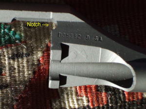
As an example of how arcane this process gets, look at
the details of an operating rod in this pair of pictures.
The upper picture shows the bolt lug housing,
with a squared off straight-sided hump.
That means it was one of Types 6A through 11.
The lower picture shows that it is stamped with
the drawing number
D36382 9-SA.
The flat surface on the bolt lug housing combined with that
drawing number means that this particular operating rod
is of Type 6A, meaning that it was manufactured for a
rifle with receiver serial number in the range
3,450,001 through 3,850,000,
and in turn, that it was manufactured some time in
January through June of 1945.
However, notice the rounded notch labeled in the lower picture — that rounded notch would have been added in a post-WWII modification intended to relieve stress at what had previously been a square corner prone to breakage over extended use.
Amazon 1888722037

Amazon 1888722134

