Restoring an M1 Garand Rifle
Final Assembly
Amazon B00KSJ9ZBI
Final Assembly
We are finally ready to assemble our M1 Garand rifle! We started with a receiver from ODCMP, a new barrel, and a parts kit including all the other components including a stock. We assembled the barrel into the receiver and reamed the chamber to its proper dimensions. Then we parkerized most of the parts and restored the wood stock. Now it's time to put it all together.
This should be pretty straightforward if you do things in the right order. Garand gurus will see that I wandered down some blind alleys, putting things together too soon and then disassembling and backing up a few steps.
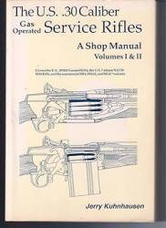
For far more details, see Jerry Kuhnhausen's The US .30 Caliber Gas-Operated Service Rifles, a nicely detailed armorer's manual. Or, for a much simpler version, the Gun-Guides volume.
Amazon B0006F5XOW

Amazon 1934044253
For example, the rear handguard needs to be installed very early in the overall process.
Only after the rear handguard is installed can you slide the lower band onto the barrel and then drive (ideally, press) the pin into place to hold it there.
Then the forward handguard and its liner and ferrule slides onto the barrel, and only then can the gas cylinder assembly be placed on the muzzle end of the barrel.
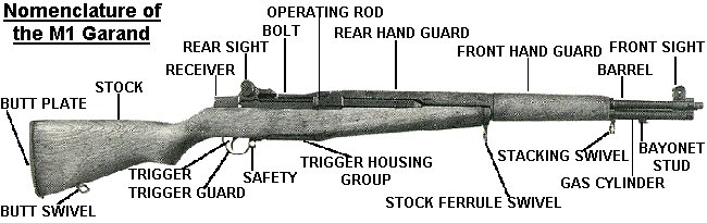
Below is the official terminology for the parts:

Below is a half-scale GIF version of an exploded diagram from a manual. Click on the image for the full-sized version.
The above exploded diagram shows it completely broken down. However, the Field Manuals are just going to discuss field-stripping and disassembly into major assemblies. They certainly aren't going to get into disassembling the trigger group and bolt! For good illustrated explanations of how to fully disassemble and reassemble an M1 Garand, see these Civiliam Marksmanship Program pages:

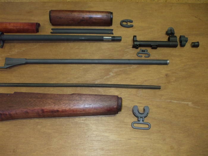
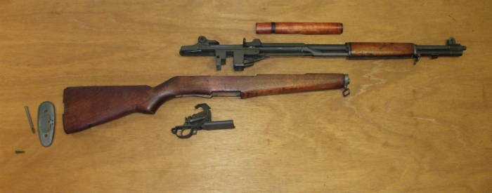
Here we go — all the parts are laid out approximately in their relative positions.
Sort of a live exploded diagram.
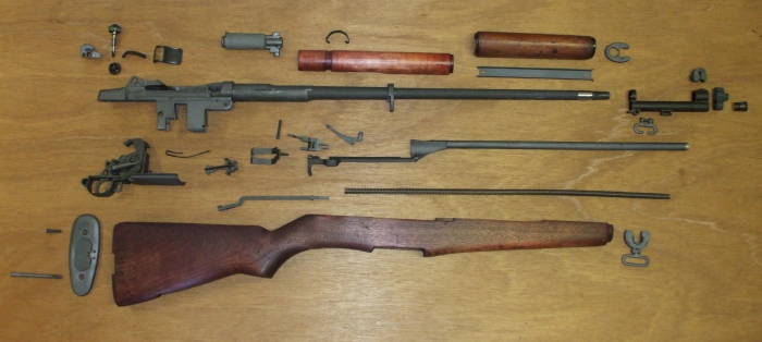
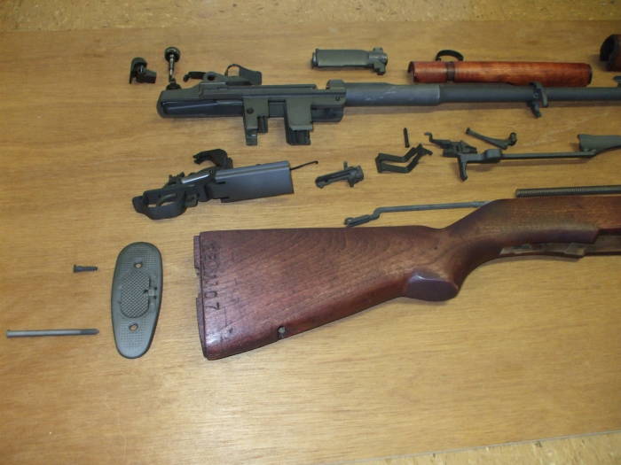
The parts in the rear half are seen here a little more clearly.
Still missing in this picture but added since — the butt swivel, the anchor point for the long screw holding the bottom of the butt plate in place.

The parts for the front half are approximately in their relative positions.

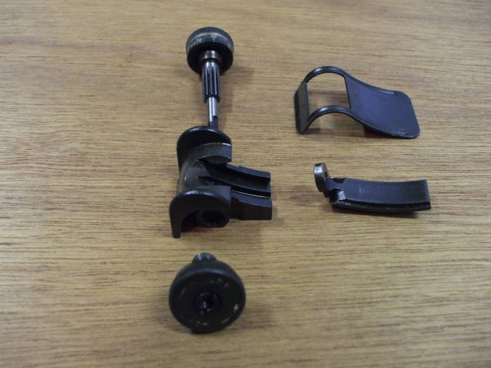
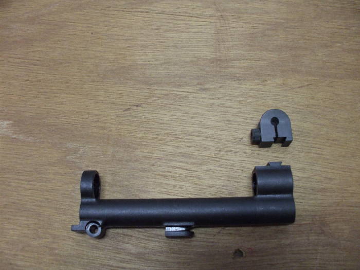
Components of the rear sight appear in their own little exploded diagram.
At left, top to bottom:
Elevating knob and pinion
Rear sight base
Windage knob
At right, top to bottom:
Rear sight cover
Aperture
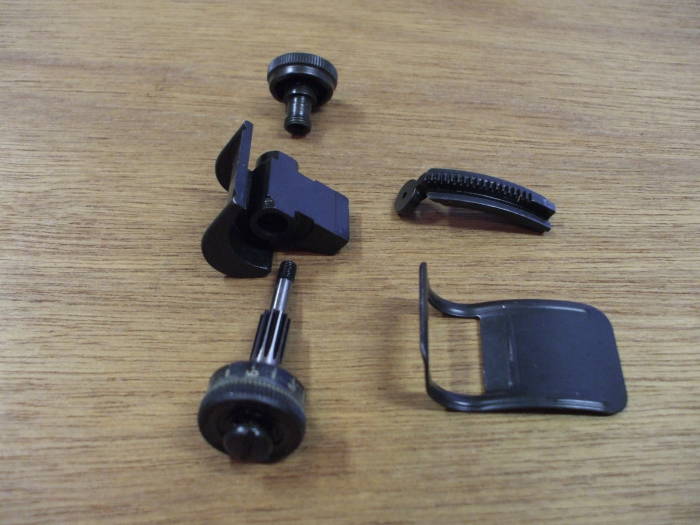
The rear sight components again, this time as if seen from below.
At left, top to bottom:
Windage knob
Rear sight base
Elevating knob and pinion
At right, top to bottom:
Aperture
Rear sight cover
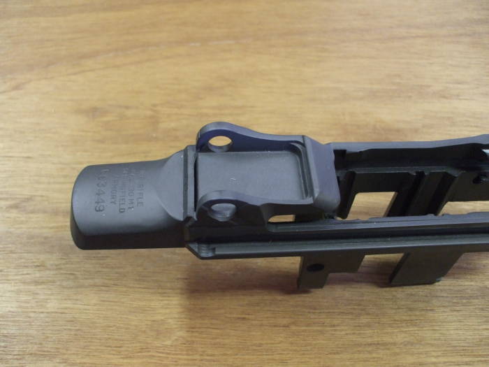
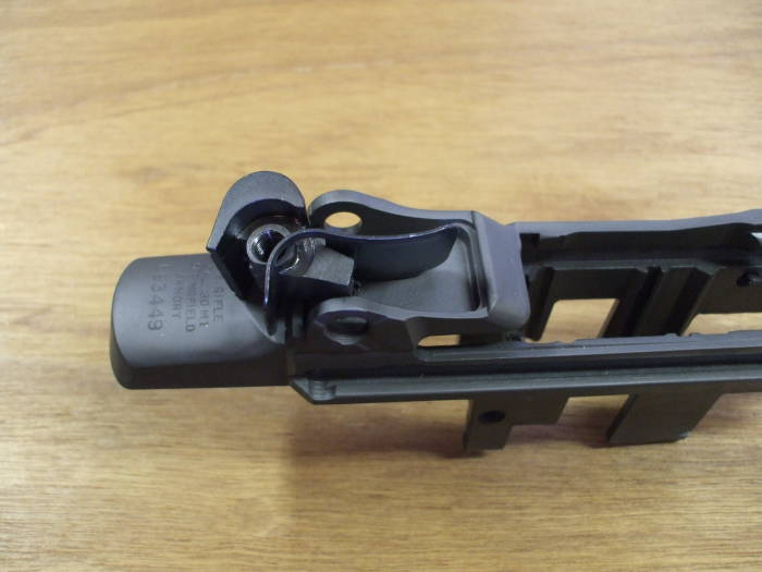
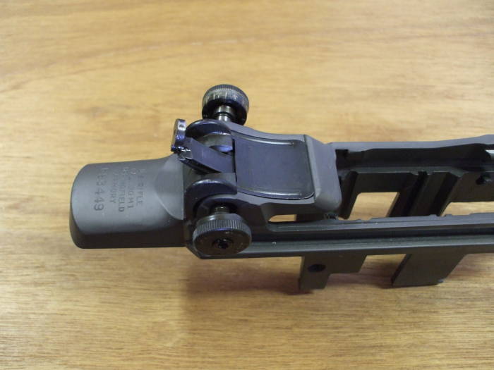
Here you see a sort of pocket where the rear sight installs on the receiver.
The rear sight cover snaps into the slots at the front and rear of this pocket.
A fine star-like pattern of notches stamped into the "ear" on the left side (the far side, not visible here) form detents for the finely space "clicks" of the elevating knob.
Four relatively large and smooth bumps on the outer face of the "ear" on the right side (dimly visible here) form detents for four "clicks" per revolution of the windage knob.
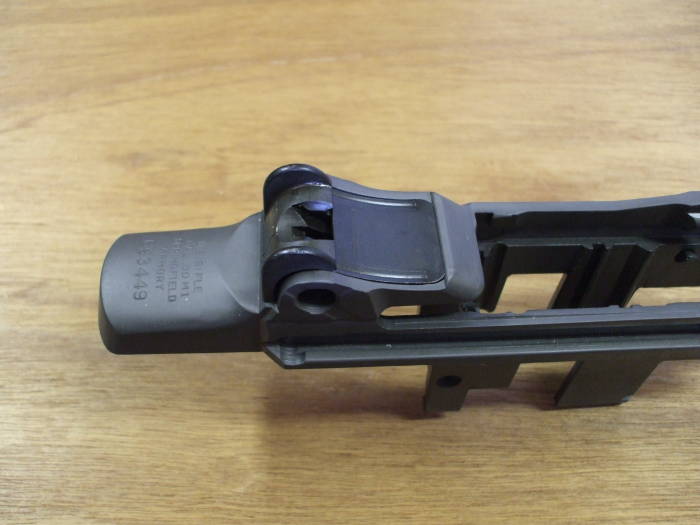
The rear sight base and cover are about to be installed in place.

The rear sight cover has been snapped into place, holding the sight base more or less in the correct position and orientation.
The aperture is being slid onto position.
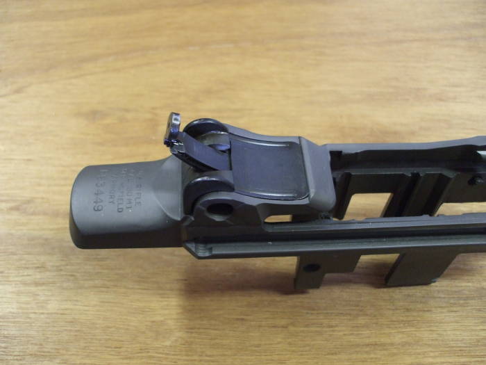
The windage knob (near side) and elevating knob and pinion (far side) are being slid into place.

The windage knob threads into the right sight base.
The elevating pinion screws into that.
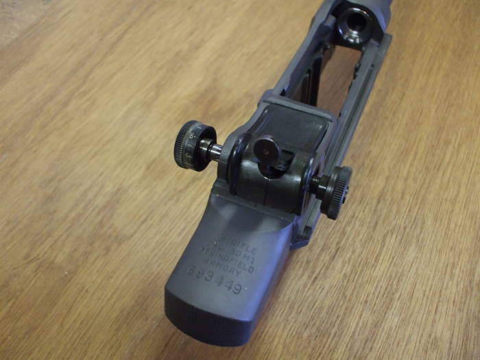
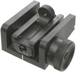
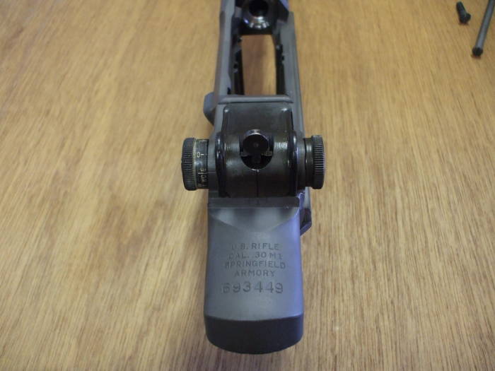
The rear sight is finally assembled and ready to be zeroed!
Turning the windage knob (at right) moves the rear sight base left to right and the aperture rides with it.
Turning the elevation knob engages the elevation pinion, and the aperture moves as a rack in, well, a rack and pinion arrangement.

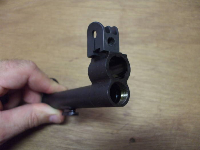
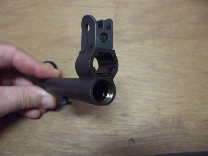
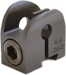
The front sight attaches to a dovetail on the forward ring of the gas cylinder.
The gas cylinder itself is made of stainless steel because of the temperatures involved.
That was good from a metallurgical point of view, but it causes problems in combat when a rifle includes a highly reflective part.
Some sort of blacking was typically applied, either a coating (even carbon from a candle flame) or a chemical treatment.
The front sight slides onto the dovetail and the allen screw is tightened. That compresses the slit body of the sight onto the dovetail. The second picture shows that the allen screw has been tightened.
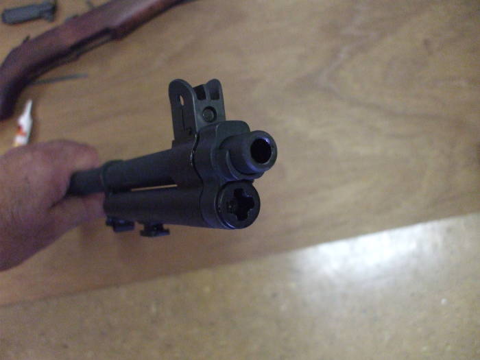
A gas port in the bottom of the barrel aligns with a larger hole through the cylinder in the bottom of the front ring.
The gas cylinder plug will be screwed into the finely threaded cylinder. This forces the hot gas to expand to the rear against the short piston forming the front end of the operating rod.
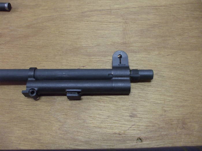
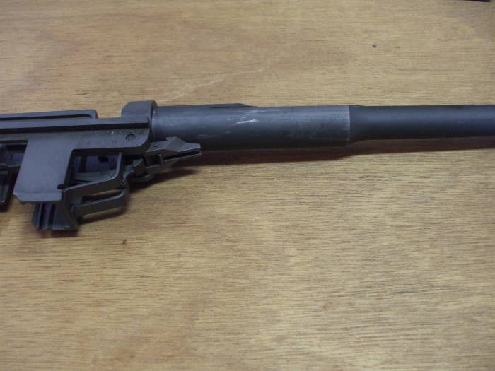
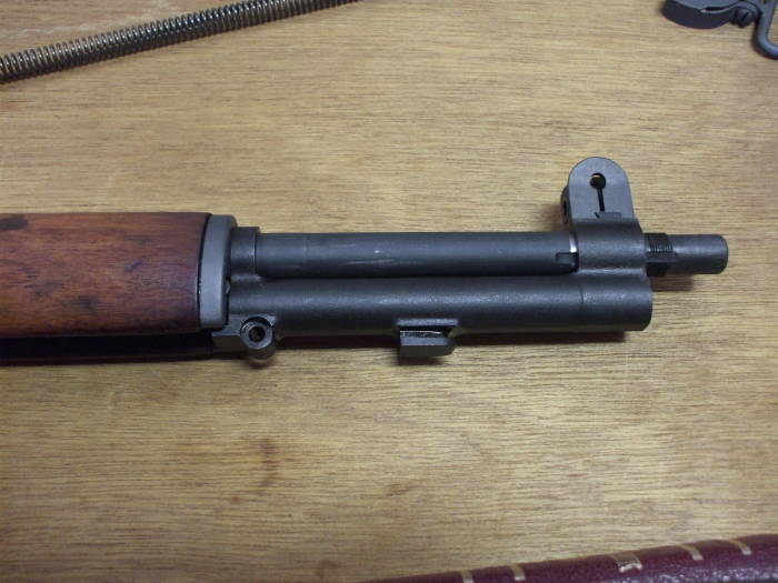
The gas cylinder assembly slides onto the barrel. The non-parkerized region near the muzzle will be within the front ring of the cylinder.
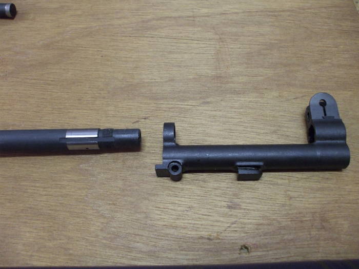

Three splines at 120° spacing on the barrel mate with corresponding ridges in the front ring.
It's a very tight fit!
It was too tight on mine at first. It would take some vigorous smacks with a heavy hammer against a piece of scrap wood to drive the gas cylinder onto and off the barrel.
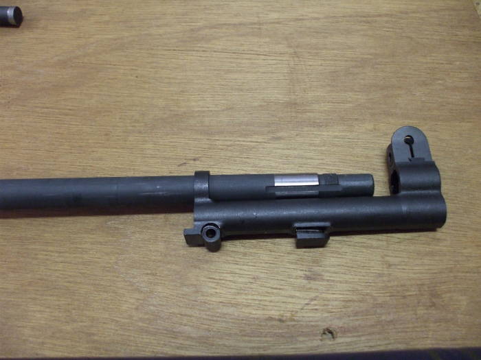
I wrapped the barrel with masking tape immediately in front of and behind the shiny band seen here. It's of slightly larger diameter than the rest of the barrel.
I then used fine (#200) metal oxide sandpaper to smooth this area to the point that the circumferential mill marks disappeared.
You have to rub along the length of the barrel, hence the masking tape. Attempts to run around the barrel just turn this into an exercise of convering sandpaper to regular paper because of the slots mating with the splines of the gas cylinder.
The result was that the gas cylinder could be installed and removed by hand, but it is not at all loose.
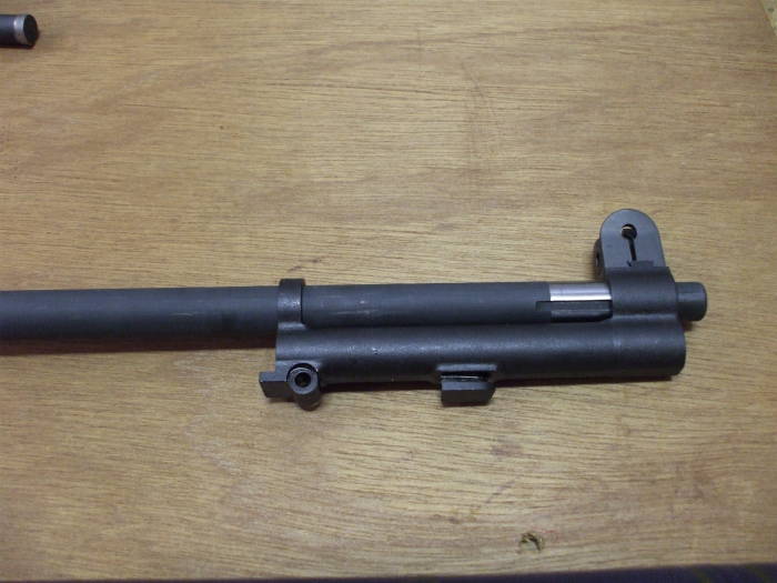
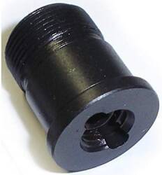
The threads on the barrel will engage the gas cylinder lock.

The gas cylinder lock threads onto the barrel, stopping when its non-threaded ring is aligned with the gas cylinder.
The gas cylinder plug is then inserted through the gas cylinder lock and then threaded into the gas cylinder.
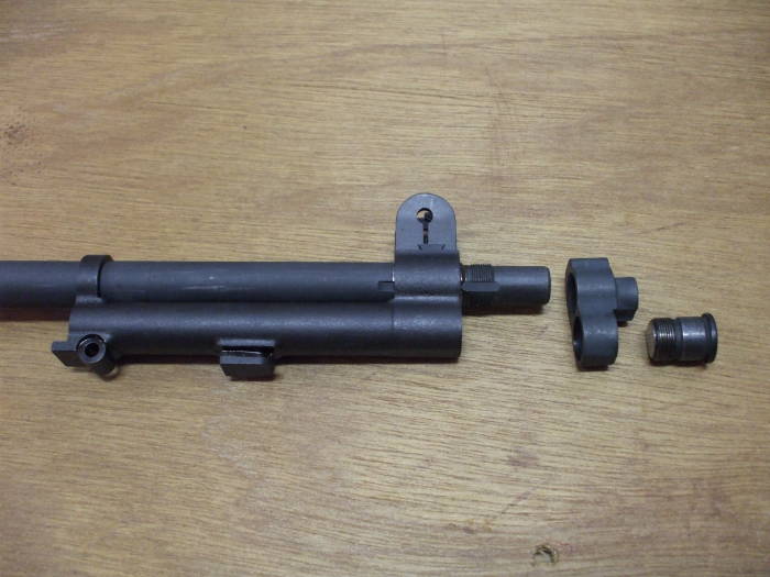
The complete gas cylinder assembly in place!
Of course, as I said above, all this will have to come off. Everything else must be installed on the barrel first. The gas cylinder must be the last thing slid on from the muzzle end.
Duh.

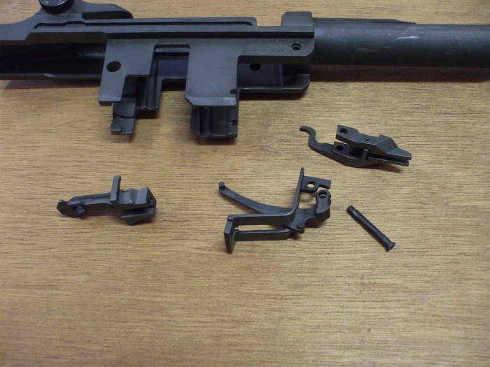
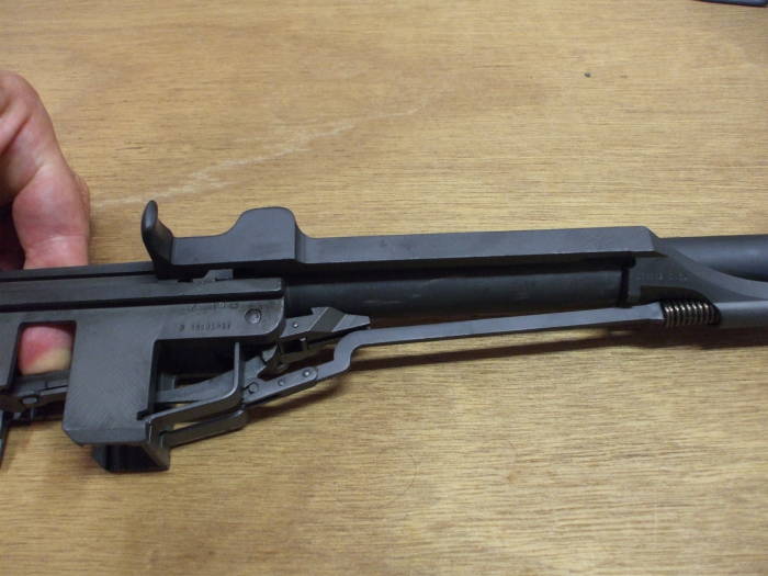
Now it's time to figure out the action....
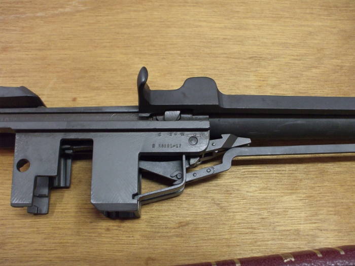
Left to right below the receiver we see:
The follower.
The bullet guide above the follower arm.
The operating rod catch assembly above the follower arm pin.
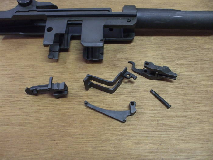
The follower arm passes through the bullet guide.
The follower arm pin will pass through the holes at the front of the receiver and through the large holes in both the follower arm and bullet guide.

Well, it's more complicated than that....
The follower arm pin will also pass through the operating rod catch assembly.
The follower arm pin passes through, in order:
Receiver right wall
Catch assembly right arm
Follower arm right hole
Bullet guide
Follower arm left hole
Catch assembly left arm
Receiver left wall
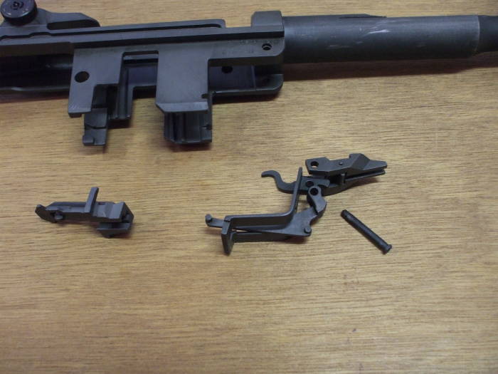
The action components are in in their relative positions but not in the receiver. The follower arm pin has been passed through their mutually aligned holes.
The two small pins at the rear end of the follower arm slide into a slot in the bottom face of the follower. The square bars at the sides of the follower, one just visible here, slide into vertical slots in the "legs" of the receiver.
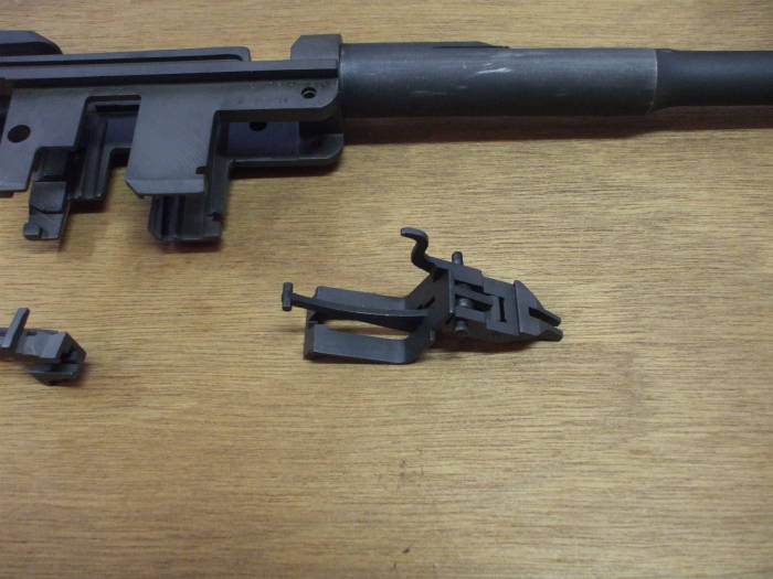

Here are the action components assembled to each other but not assembled into the receiver.
You can see the holes through the receiver for the follower arm pin directly above the pin, and the slots for the follower in the inner faces of the forward "legs" of the receiver.
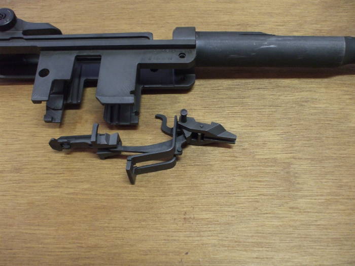
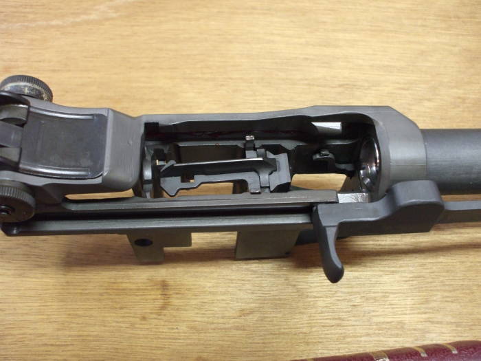
Enough experimenting, here are those action components fully assembled.
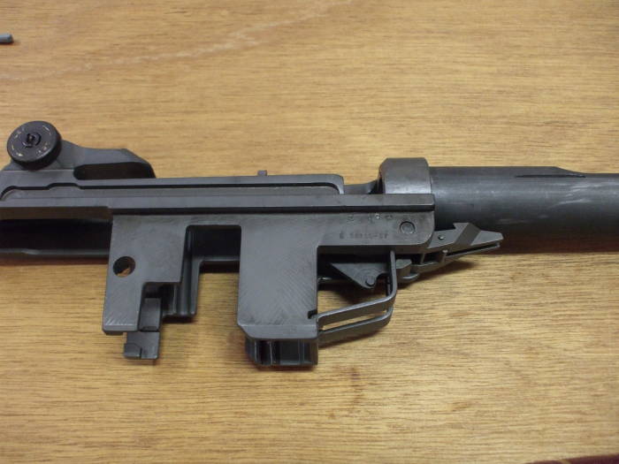

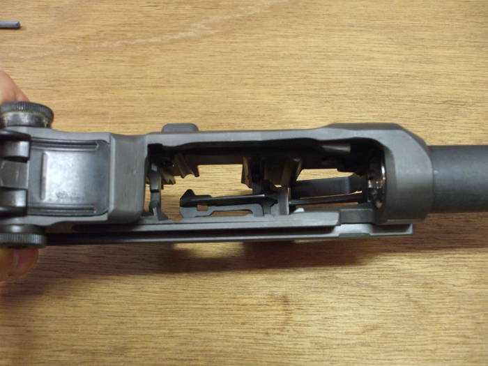
And as seen from above....
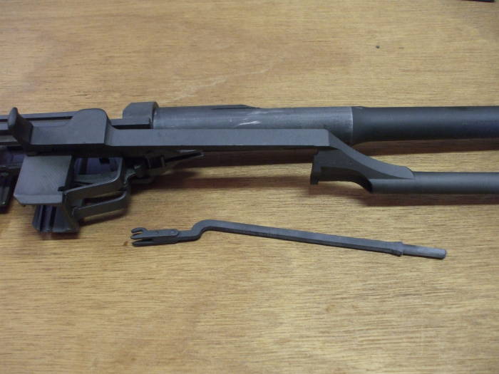
The barrel and receiver, with the operating rod catch immediately below the chamber end of the barrel.
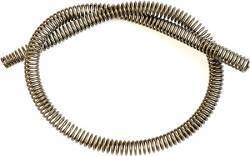
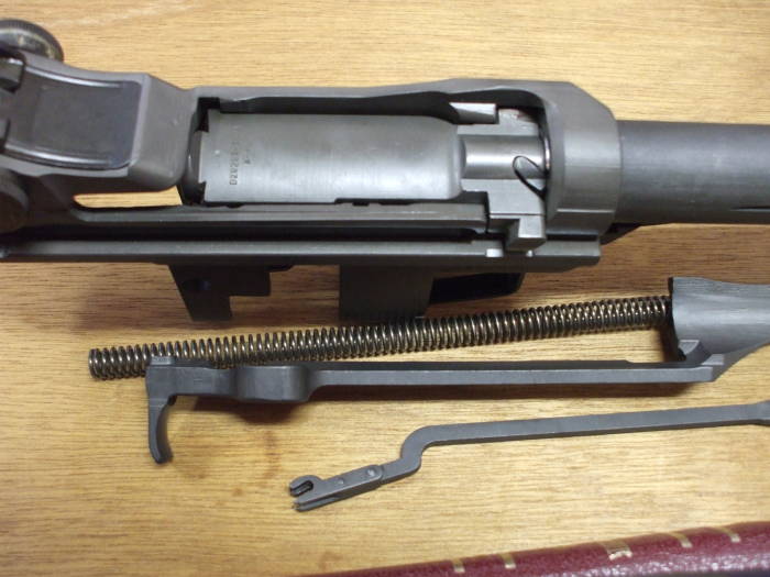
The operating rod (above) and follower rod (below)

The operating rod in place with the operating rod spring being inserted into it.
The front part of the operating rod is a hollow tube ending in a short piston.
The spring will attempt to simultaneously press the operating rod (and therefore the bolt) forward while pressing the follower rod back (and therefore levering the follower arm up).
Raising the follower arm feeds the next round when the bolt cycles.
Pulling the bolt forward strips that round off the stack and chambers it.
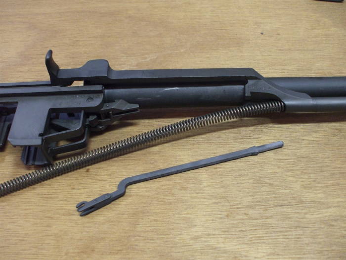
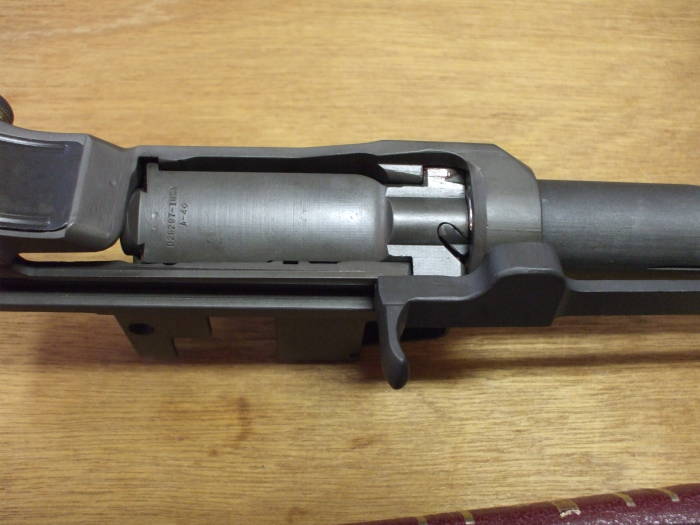
The operating rod, operating rod spring, and follower rod in place.
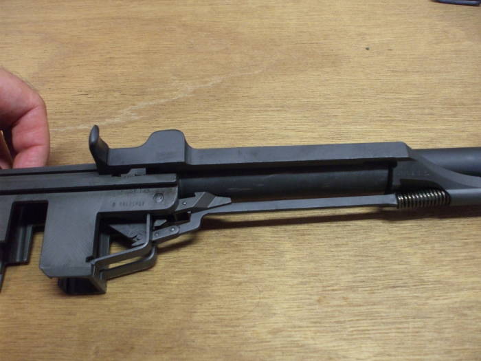
The operating rod, operating rod spring, and follower rod in place, with the follower itself manually depressed as if a full en bloc clip of ammunition were loaded.

Top view of the action.
Whoops, where's the bolt? That needs to be installed before the operating rod....
OK, remove the operating rod, spring, and follower rod. Put the bolt into the receiver and get ready to put it all back together.
I told you this was out of order in places.

That's better.
And a side view.

Now I've backed up a few steps to remove the gas cylinder and put parts on the barrel in the correct order.
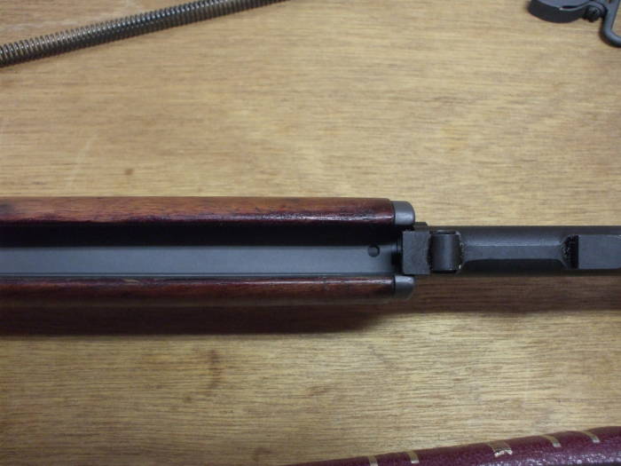
Here you see the front half of the front handguard and the gas cylinder assembly.
The same thing as seen from the bottom.
The thin sheet metal front handguard liner is visible.
It can be installed two ways but only one of them works — the liner surface itself should be against the barrel so there is room for the operating rod.
I'm getting close, here are some major subassemblies.
Close, but not quite there — the rear handguard isn't installed!
Pull the gas cylinder and front handguard off the barrel, push out the pin holding the lower band in place, and pull it off.
Then put everything on in the right order.
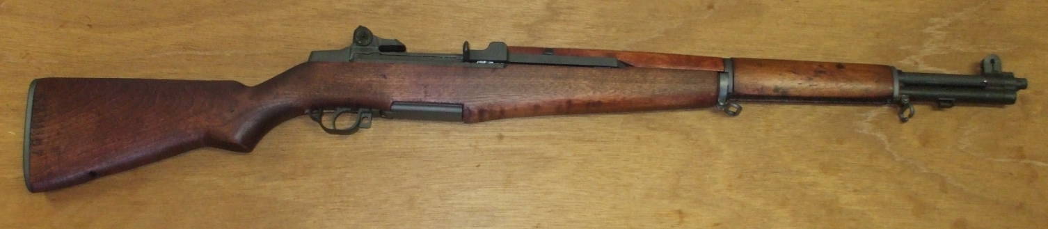
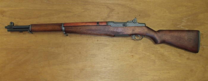
OK, finally it's complete!
From the right....
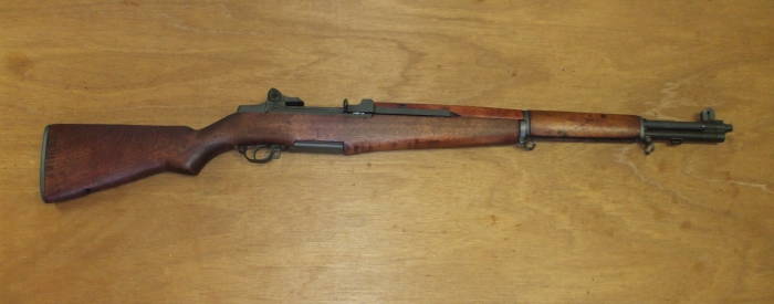
.... and from the left.
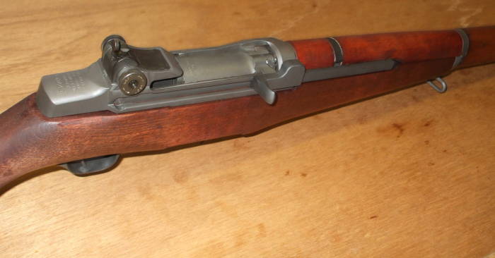
The receiver area.
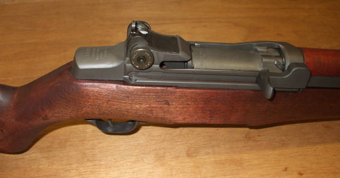
The receiver area and all the stock components.
The rear handguard is still relatively orange, but the matching depends on the light.
It appears that the camera flash makes for a worst-case appearance.