M1 Garand Gas Pressure and the Operating Cycle
M1 Garand Gas-Operated Design
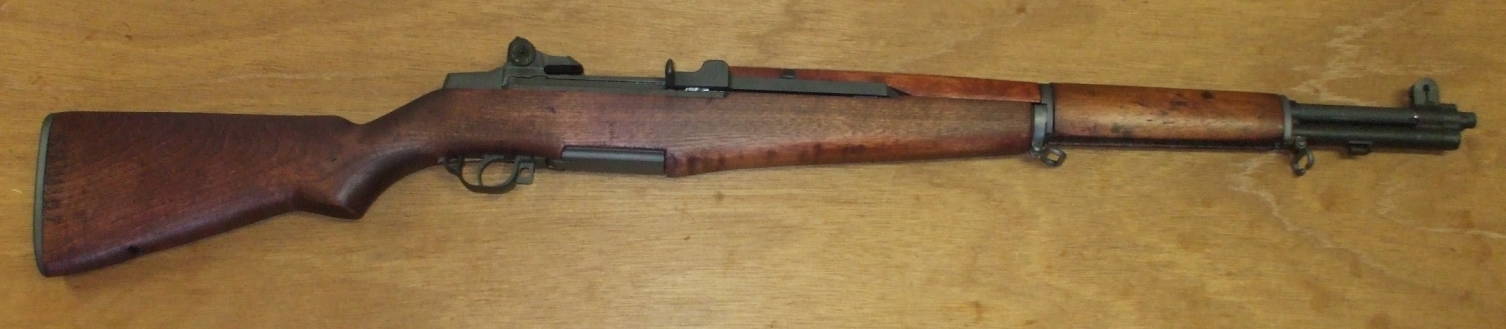
The M1 Garand rifle is a semi-automatic design. It fires a single round each time the trigger is pulled, using some of the power of that round to cycle the action, ejecting the spent cartridge and chambering the next round. It operates by using some of the expanding gas from the fired round to cycle the action. Designed in the 1920s, it was the world's first semi-automatic rifle generally issued to infantry.
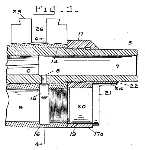
Diagram from U.S. Patent #2,287,032, "Barrel And Gas Cylinder Assembly For Firearms".
The gas is diverted from the barrel through a small gas port into a gas cylinder. A piston is nearly all the way forward when the round is fired, making for very small volume within the cylinder.
The gas pressure against the piston head forces it back in the cylinder. The piston is the forward end of the operating rod, which extends back to the receiver where it engages a lug on the bolt to unlock it through rotation and move it backward to extract the spent cartridge case from the chamber. That case is ejected and the hammer is cocked in preparation for firing the next round. The operating rod and bolt then reach the rearward end of their travel, and the main operating spring pulls them forward again. If another round is available, it is chambered as the bolt and operating rod return to their original position.
The diagram from John Garand's U.S. Patent #2,287,032 shows a cross section of the muzzle area. 6 is the rifled barrel bore, and 7 is the optionally unrifled final 1.5" or so of the bore.
The gas port is the small hole 8, and 9 is the interior of the gas cylinder (15 and 16 show an annular ring making the very front of the gas cylinder slightly wider).
21 and 20 plus the threaded section to the left of 20 are the gas cylinder plug.
The gas cylinder is made from stainless steel to withstand the corrosive effects of hot gas under high pressure. That unfortunately makes for a fairly large highly reflective part near the muzzle. Chemical treatment can darken the outer surface, but remember that the material is called stainless steel because it is difficult to change its color. The gas cylinder would become shiny over time. Men in the field would re-blacken their gas cylinders with smoke from a campfire, candle, or trusty Zippo lighter.
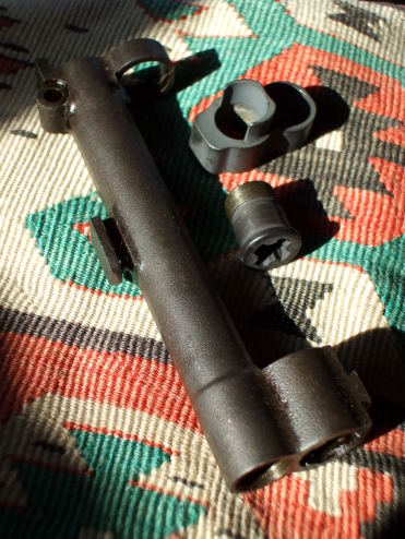
Clockwise here you see a gas cylinder, gas cylinder lock, and gas cylinder lock screw.
The gas cylinder is slid into place on the barrel. The gas cylinder lock (see 17 and 19 in the cross-section diagram above) threads onto the barrel. The gas cylinder lock screw is inserted through the gas cylinder lock, preventing it from turning and unscrewing, and the screw is threaded into the front of the gas cylinder.
The rear surface of the gas cylinder lock screw forms the front wall of the gas cylinder.
Here we see just the gas cylinder, lock, and lock screw assembled together.
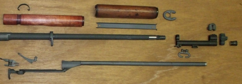
Below is a disassembled M1 Garand with the parts laid out as if in the form of a physical exploded diagram. The operating rod is the long object across the bottom. The shiny cap at our right (forward) end is the piston head itself. The angled piece at our left (rear) is the operating rod handle — this is the handle by which the action can be manually cycled.
The shiny segment of the barrel exterior was not parkerized, that surface was protected by high-temperature RTV sealant to keep the surface "in the white". The barrel slides through the two rings on top of the gas cylinder so that untreated shiny surface is within the front ring of the gas cylinder.
The gas cylinder lock threads onto the barrel, and the gas cylinder lock screw is inserted through the lower loop of the lock to thread into the front of the gas cylinder.
A later assembly step then inserts the piston end of the operating rod into the gas cylinder.

Amazon 0811703509

Amazon 1934044253
Gas Pressure During Firing
The bullet exits the muzzle at about 2650-2700 feet per
second.
That means that only a little less than 50 microseconds elapse
between when the rear of the bullet passes the gas port and
when the bullet fully exits the muzzle.
1.5 inches = 0.125 feet
0.125 feet × ( 1 second / 2650 feet ) = 0.000 047 seconds
0.125 feet × ( 1 second / 2700 feet ) = 0.000 046 seconds
During that brief time, the gas cylinder is part of the highly
pressurized space behind the accelerating bullet and the
pressure within the cylinder is increasing very rapidly.
The large momentum of the operating rod renders it effectively
motionless during this period.
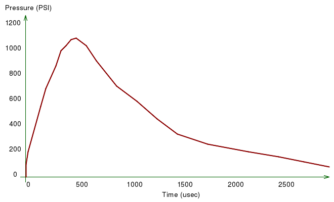
Typical M1 Garand gas cylinder pressure curve.
After the bullet has left the barrel, the gas pressure within the barrel is still much higher than ambient. Much of it flows out through the muzzle, the so-called "muzzle blast". Watch the grass in front of someone shooting from the prone position! However, gas will still flow out of the barrel through the gas port as long as the pressure within that region of the barrel is higher than that within the gas cylinder.
The pressure within the cylinder is higher than the exterior pressure, that behind the piston, so the piston and operating rod begin to accelerate toward the rear. The Garand piston-cylinder system is lossy, some gas will flow around the piston to exit the rear of the gas cylinder, but enough force is applied to operate the action.
After about 500 microseconds for most combinations of gas cylinder assemblies and ammunition, the pressure reaches its peak. The piston is now moving toward the rear and expanding the volume within the cylinder. Meanwhile, the gas flow from the barrel through the port is rapidly slowing.
Recall the ideal gas law: PV = NkT
P = absolute pressure
V = volume
N = number of particles of gas
k = Boltzmann's constant
T = absolute temperature
The volume started out very small, so a small rearward
movement of the piston would make for a significant increase
in volume and corresponding decrease in pressure
if no more gas were flowing in.
The pressure within the cylinder continues to drop until about 3000 microseconds (or 3 milliseconds) have elapsed, at which point is it close to the ambient pressure. At this time the operating rod has moved approximately 3/8 of an inch. In this brief time and space of motion it has been accelerated to a velocity that allows its momentum to carry it to the rear to unlock and retract the bolt, extract and eject the spent cartridge, and cock the hammer.
Impulse is the integral of a force over time, it is the measure of the change in momentum applied to a body. The force would be the gas pressure multiplied by the area of the piston face, so the impulse or momentum transfer is proportional to the area under the above gas pressure curve.
The impulse is the integral or the area under that curve. The precise shape doesn't matter, you just need the area corresponding to the needed momentum transfer to get the operating rod moving at the needed velocity, Consider the difference between a regular hammer and a dead-blow hammer. Or, the difference between hitting something with a hammer and pushing against it.
Controlling Gas Pressure With A Ported Gas Plug
Many modern commercial .30-06 cartridges are loaded more powerfully than the original M2 ball ammunition for which the Garand is designed. If you use commercial ammunition you could damage the operating rod or cause even worse problems. The solution is a replacement gas plug screw.
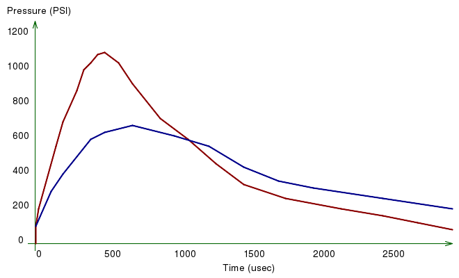
Typical (red) and modified (blue) M1 Garand gas cylinder pressure curve.
GarandGear has developed a ported gas plug that significantly changes the shape of this curve. An operating rod can be damaged by overly high gas cylinder pressure causing excessive force against the piston at its front. Poor lubrication or mechanical binding of its movement can also cause damage, and notice that they directly lead to higher gas cylinder pressure as the piston is unable to accelerate rearward as quickly.
The red curve here shows a typical pressure curve with the original gas cylinder lock screw design.
The blue curve shows a typical pressure curve when the lock screw has been replaced with one with a deep cylindrical cup instead of a flat face. This increases the initial volume in the cylinder, and because to that PV = NkT law the peak pressure is significantly reduced. While they call this a "ported" gas plug, that does not mean that it vents gas and loses potential impulse. The port is that newly available volume within the rear body of the screw.
The action still cycles reliably because the pressure stays higher in the later phase of the cycle. The area under the blue curve, the impulse, transfers about the same amount of momentum.
See GarandGear's article on shooting commercial ammunition in your M1 Garand for much more detail, including many pressure curves like these measured on various factory ammunition.
History of the Garand Gas Screw
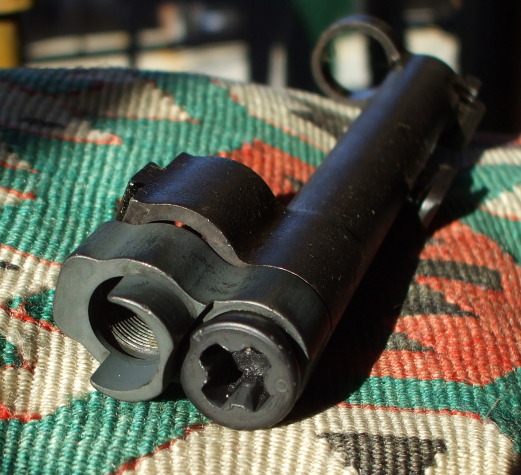
The original Type 1 gas screw design was defined in drawing number B147428. It was machined from a solid piece of stainless steel, and had a single slot for a large screwdriver blade.
The Type 2 (defined in drawing number B147851) had a "non-return valve" and can be spotted by the cross-shaped screwdriver slot with a 0.280" hole at its center. The M7 grenade launcher had a stud that, when mounted on the barrel, protruded into this central hole and opened that valve. That allowed gas to escape, lowering gas cylinder pressure and reducing what would have been excessive rearward momentum of the operating rod. That excess momentum would cause the rear of the bolt to hammer against and damage the rear of the receiver.
Type 3 (defined in drawing number B7310079) had a "poppet valve". It was used in the same way for the same reasons, and can be distinguished from the Type 2 by a "P" marking on their front face.
Springfield Armory manufactured the solid Type 1 lock screws throughout World War II, along with Type 2 (serial numbers 1,470,000-2,500,000, so Nov 1942 — Jan 1944)) and Type 3 (serial number 2,500,000 or Jan 1944 to the end of production). After January 1944, all had the Type 3.
Winchester manufactured Type 1 lock screws exclusively, except for a range of just 40,000 in 1945 which had the Type 3. International Harvester and Harrington & Richardson manufactured Type 3 lock screws only.
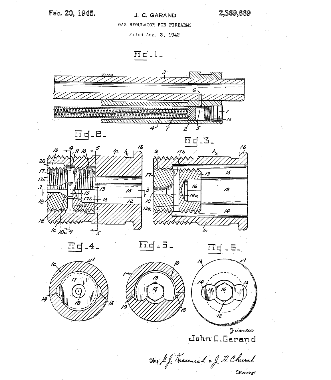
John Garand patented a venting gas screw in 1945, it was issued U.S. Patent US2,369,669 A.